1 û Title
of the experiment and Team name
Title: Light Backscattering Measurements of Small Particles in Microgravity
Team Name: Scattering@Zero-g
2 û
Experiment objectives
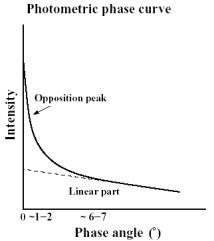
The objective of this experiment is to get experimental data of the backscattering properties of dust particles in microgravity. The data will then be compared with similar data measured in 1 g environment in order to gain better understanding of the effect that the packing density of dusty material has on its light scattering properties. The experiment is specially designed to measure the lightcurve near and at zero phase angle i.e. the angle between the observer and the measured object as seen from the light source. In astronomy, many light curve measurements are done at near zero phase angles (in opposition) because the scattering surface area of the measured object is largest. A good example of an opposition is the full moon, which almost reaches zero phase angle (in this case, the lunar eclipse is observed at zero phase angle). A very interesting phenomenon has been observed happening, when the object is near the zero phase angle. The intensity of light from the object is increasing linearly with decreasing phase angle due to the increasing scattering area. However, when the phase angle reaches ~5 degrees the light curve turns nonlinear, almost exponential. This phenomenon is called the opposition effect and the most pronounced part of it the opposition spike. Theoreticians have tried to explain this and the negative polarization accompanying the effect for over a century, but have thus far not succeeded. It can be considered as one of the remaining big mysteries in classical physics. Many theories have been created, which take into account shadowing effects (the scattering surface is rough and has shadows that disappear at zero phase angle) and multiple scattering (the scattered electromagnetic field can penetrate the surface, scatter multiple times and possibly gain strength in certain phase angles).
A serious problem for creating a rigorous model of backscattering is that there are no experimental measurements of a well defined dust material near and at zero phase angle in microgravity. This is important because we have loads of measurements from atmosphereless, dusty bodies in the Solar system showing this effect[1]. Dust, with particle sizes from about 1Ám to 1mm, is thought to be a major constituent in multiple scattering.
Of all physical parameters that have an effect on light scattering (particle size, shape etc.), packing density is the only one whose effect can not be measured in 1 g. A variety of different kinds of dusty materials have been measured in earthbound laboratories, but the link between 1 g and 0 g environment can not be established without similar measurements in microgravity.
Most models predict that the
decrease of packing density in the material increases the opposition effect. The aim of this experiment is to get the
first set of data for light scattering near and at zero phase angle for a well
established dusty material (either boron carbide (B4C) or aluminium oxide
(Al2O3)) which have both been thoroughly measured at the University of Helsinki
using similar kind of experimental setup[2].
Afterwards, careful examination will be conducted in order to establish the
nature of the effect that the absence of gravitational forces has on the light
curve.
Having a robust light scattering theory has fundamental astronomical applications. Remote sensing of atmosphereless solar system bodies needs scattering theories to help understand the data. For example, ESA lunar mission SMART-1 has a advanced imaging system AMIE[3] which produces data of opposition region. Having laboratory data of scattering in small g environments helps us link SMART-1 data to physical parameters i.e. to Lunar surface properties. The list of applications is very long.
Working theories about scattering of light have also important industrial applications. The optical properties of different kinds of surfaces, e.g. papers and different kinds of paints, depend on the scattering properties of small particles on the surface. Without proper light scattering models it is impossible to gain desired optical properties by numerical methods.
3 û
Experiment description
Scattering measurements have and are being done in other phase angles in microgravity (e.g. PROGRA▓ Parabolic flight campaign[4], ICAPS proposal for the ISS) but they all have a serious restriction: they cannot measure very small phase angles. The problem is, that in conventional experiments the detector gets in front of the light source in small phase angles thus effectively blocking the light. Our experiment makes use of a novel idea which allows us to reach even the zero phase angle.á
The big innovation in this
experiment is the use of a beamsplitter (a mirror, which permits half of the
incident light to pass and reflects the other half), see picture below.
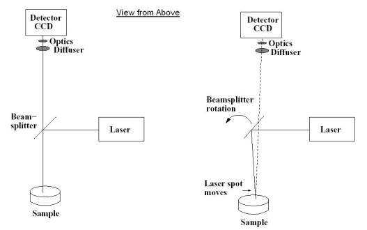
By changing the angle of the beamsplitter it is possible to get different kinds of phase angles. The aim of this experiment is to measure phase angles in the previously unattainable phase angle region between 0 and 5 degrees.
The light source is a commercial type diode laser (λ=670 nm, 5ÁW). The sample is in a sealed glass container, whose optical properties have been carefully calibrated in laboratory. The packing density of the sample in microgravity can be calculated from the volume of the container and the mass of the sample. The sample is shaken manually before every measurement to distribute the material evenly in the container.
The detector is a professional grade SBIG ST-8 CCD-camera which has optics adapted from commercial 35mm-film camera. There is also an optical diffuser in front of the optics to avoid possible saturation of the CCD-chip (over exposure). The detector is controlled by a laptop pc.
The aim is to take three exposures at every phase angle to gain an acceptable error estimate. Only one exposure can be taken in one microgravity phase because the readout time of the CCD-camera is ~15 s. The total amount of angles measured is thus the amount of parabolas divided by three. The measurements are done as differential photometry i.e. a white reference plate is measured at every angle for comparison. The white reference plate this experiment is using is a widely used SpectralonÖ plate.á
4 û
Technical description of the experiment set-up
A similar experiment setup has
already been built and used for
measurements at the
Observatory, University of Helsinki. Our purpose is to build a similar
experiment, but
with the modifications needed for parabolic flights (smaller size, casing,
attachment, etc.). The testing and calibration can, and will, be performed in
1g.
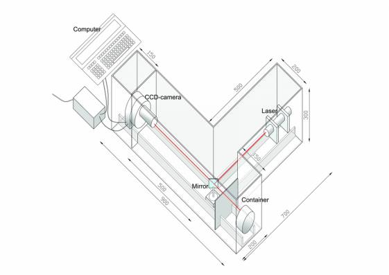
The technical setup for the experiment
consists of five elements mounted on a single rack, which in turn is mounted
on the attachment rails. The five elements are a CCD-camera with needed optics (all in one piece), a diode laser, a beamsplitter attached to an adjustment tool, the sample container, and a
laptop computer controlling the
CCD-camera. The image below shows the setup. Note that the setup is lying on
the floor, so the vertical space needed is minimized.
The setup is mounted on a rack made of U-profile aluminium bars and covered
with two rectangular wooden tubes from the CCD-camera to the sample container
and from the laser to the beam splitter. The tubes have three purposes: (1)
they prevent diffuse background light from interfering with the measurements,
(2) they prevent the laser beam from getting out from the experimental setup
and (3) they form a protective casing for the experiment. The laptop is
attached to the aluminium bars with L-shaped attachment bars right next to the
rest of the experiment setup.
5 û
Installation of the experiment in the aircraft
The overall dimensions for this experiment are 1m x 0.8m x 0.4m. It will take up the space of one rack. The maximum total weight of the experiment will be 16 kg. Some values can vary little after we start building the experiment. The values given are expected maximum values.
6 ûElectrical
The experiment detector has a power consumption of 6 VA at 220 V and the
laptop pc needs 330 VA at 220V. The total power consumption is 336 VA at
220V.
7 û Mechanical resistance of
the experiment
We are planning on fastening the experiment down using the standard rack attachment boltholes. There are no free floating objects.
8 û In flight procedures and
in flight personnel
|
Flight
Phase: |
Team
Member 1: |
Team
Member 2: |
|
level
flight |
Manages
the computer, takes calibration images |
Changes
phase angle if necessary, |
|
|
when
necessary |
arranges
calibration setup when necessary |
|
|
|
|
|
1.8
g |
Prepares
to take the measurement |
Prepares
to take the measurement |
|
|
|
|
|
0
g |
Manages
the computer, takes the measurement |
Shakes
the sample to make it more homogenous |
|
|
|
|
|
1.8
g |
Prepares
to take calibration images |
Prepares
to change the phase angle |
|
|
|
|
|
|
To
be repeated as many times as possible |
|
9 û Hazard analysis
There are no dangerous products used in this experiment. The dust used in this experiment is totally non-toxic and otherwise harmless and is also inside a closed container. The experiment doesnÆt use any pressure systems. The glass container containing the dust could be destroyed in the case of sudden depressurization, but as it is very small and inside a protective casing, poses no considerable risk. The laser used in this experiment is class 2 (used in e.g. laserpointers) and the beam is at all times inside an optical tunnel. There are no motors etc. in this experiment. The experiment contains no unshielded electrical wiring. There is no chance for electrostatic discharge. In the case of sudden electrical loss, the experiment shuts down safely. The only electromagnetic field generated comes from the experiment laptop pc (whatever a normal pc generates).á There are no hot parts. The experiment works at the cabin temperature. All of the necessary key security items are easily accessible. No smoke or etc. comes out of the experiment. The experiment is silent and produces no smells. There is one moving part (the beamsplitter) which can not cause any injuries. We do not use human subjects for this experiment.
10 û Pressure vessel
certification (if applicable)
None needed.
11 û Vent line connection
and other requests
Do you need to use the aircraft vent line (throwing
experiments wastes out of aircraft)? : No